The AMETEK Land 4500 MkIII must be configured for the precise pathlength of the place where it will be installed. This blog explains why this is important, and what the various pathlength terms mean.
The beam of light projected by the
4500 MkIII transceiver spreads out with a divergence angle of approximately 1.5°. Because of this, the amount of light intercepted by the retroreflector and returned to the transceiver depends on the distance between them.

Figure 1 Beam Divergence
To calibrate an
AMETEK Land opacity monitor, a technician focuses it for the correct pathlength, sets it up at the required distance and adjusts the calibration parameters so that it reads 0% opacity on a clear path and 100% opacity when the beam is blocked.
As a general rule, an error of 1% in the pathlength will result in a 1% error in the measured opacity. Therefore, an instrument configured for a pathlength of 2020 mm instead of 2000 mm will read 1% opacity on a clear stack, and one configured for 2200 mm can read 10% high. Because the pathlength is so important, we need to be clear about its meaning.
We define four pathlengths that are relevant to opacity measurements, with terminology consistent with the ASTM D6216 standard. These are shown in Figure 2 below.
Flange-to-flange Pathlength is the distance between flanges which are permanently attached to the stack. Depending on the size of the duct, this can be measured with a tape measure or a laser distance meter. It is generally the value that a user supplies to
AMETEK Land on the setup sheet.
Installation Pathlength is the distance between the transceiver and retroreflector mounting flanges. It is slightly greater than the flange-to-flange pathlength as it includes the small gap used to adjust the instrument’s alignment, plus the thickness of any adaptors or shutters that are fitted between the stack flange and the instrument. This is the distance used for the instrument’s clear-path calibration and is the value given on the instrument label and on the calibration certificate.
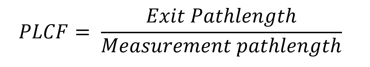
Two additional values are needed for an instrument that complies with US EPA Performance Specification 1 (PS-1). These are used to calculate the Pathlength Correction Factor (PLCF) which calculates the opacity that would be seen by an observer looking at the stack exit.
Measurement Pathlength is the internal dimension of the stack or duct at the measurement point. It is the distance traversed through the flue gases by the instrument’s light beam. It ignores the standpipes which are assumed to be filled with clean purge air.
Exit Pathlength is the internal diameter of the stack at the point where the gases exhaust to the ambient atmosphere. If the stack is not circular, a formula is used to calculate the equivalent diameter.
The measurement and exit pathlengths are only needed for instruments that have to comply with PS-1.
When you are completing the setup sheet for an opacity monitor, we require either the flange-to-flange pathlength or the installation pathlength. We can calculate the other value since we know the accessories that will be supplied with the instrument. Because this dimension is critical to the correct calibration of an opacity monitor, we will not issue an order confirmation until we have a definite value for one of these parameters.
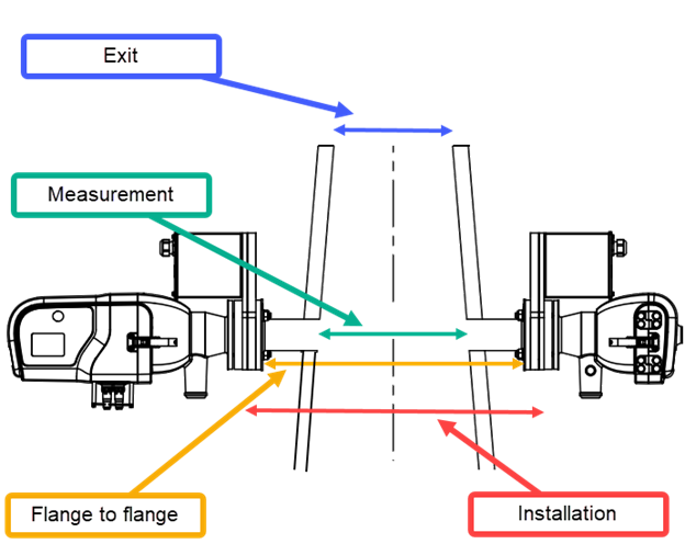
Figure 2 Pathlength definitions