We have added a simple 'Emissivity and Background Correction Calculator' to our website, and produced what we hope is useful guidance, in response to the multiple requests for clarification from end-users and after consulting with industry experts.
AMETEK Land produces the
Cyclops C100L and C390L infrared pyrometers widely used across the ethylene, refinery, petrochemical and industrial gas industries on steam cracking furnaces and steam methane reformers. Both are suited to TMT measurements due to their small spot size, high accuracy, and wavelengths that penetrate furnace atmospheres. Because of the higher wavelength of the C390L, a lower emissivity is typically required than the C100L to reduce errors between the measured and true temperatures. The resulting procedure below is a combination of AMETEK Land’s understanding of infrared physics and practical furnace experiments using the gold cup reference measurement method.
First, a quick introduction to the infrared basics. All objects above absolute zero emit radiation - the higher the temperature of the object, the higher the radiation. Infrared pyrometers
employ the Planck black body radiation law (which defines the correlation between the emitted radiation and temperature of an object) to determine the temperature of the object. Emissivity refers to the amount of radiation emitted by an object in comparison to a black body, a theoretical object with 100% emissivity. Catalyst tubes, containing endothermic gas, are grey bodies with relatively high emissivities and low reflectivity, which make them good candidates for accurate infrared pyrometry, but there are several other challenges for any measurement device (pyrometers, thermal imagers) due to incident radiation reflected off the tube from hotter surrounding surfaces (e.g., furnace insulation). This causes measured raw values to be higher than actual temperatures if emissivity alone is used to compensate and correct. Because of this, we have released the calculator below to support correction for both emissivity and background temperatures, which can be found below and on the
Cyclops product page.
 New reformer tubes can have an emissivity of around 0.90 due to their rough finish (rough surfaces typically have higher emissivities than smooth surfaces), but this often slowly reduces over time. As a standard practice, most end-users have settled on using ε = 0.85 at 1μm and ε = 0.82 at 3.9μm. Note that if a foreign material is deposited on the tube surface, e.g., refractory dust, it can affect temperatures and emissivity whilst acting as an insulative layer.
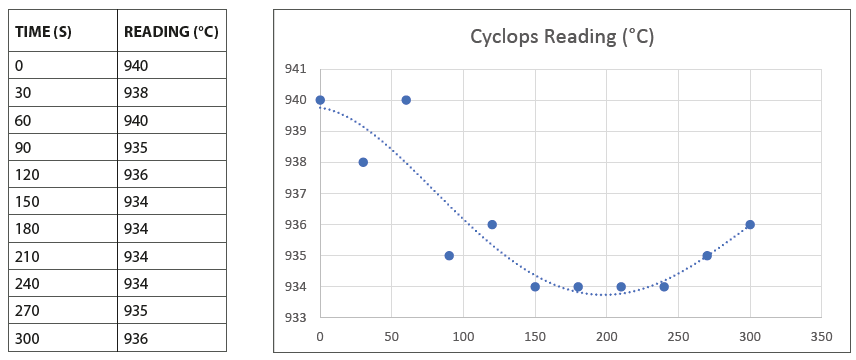
A couple of basic checks on the Cyclops are required before we begin our survey. First, check the Cyclops is in continuous/instantaneous mode as determined by the icon  . On the side LCD display panel, the selected measurement type is displayed larger and bolder than the three non-selected measurement types. The continuous/instantaneous displays the value recorded when the trigger was released and is preferable to the mean mode (which records the average value recorded whilst the trigger was held), peak mode (which records the highest value recorded whilst the trigger was held that could include refractory or multiple tubes) and valley mode (which records the lowest value recorded whilst the trigger was held that could include cold areas). During recording, your Cyclops display should look something like image on the right.
The large top-fired furnace in the diagram below is created for explanation purposes only as many questions we receive are based on this type of design. Measurements will be taken on rows 1-2, tubes 5-10 and 25-30 in burners row 2. If tubes are accessible and measurable from tube 2+, take measurements from there.
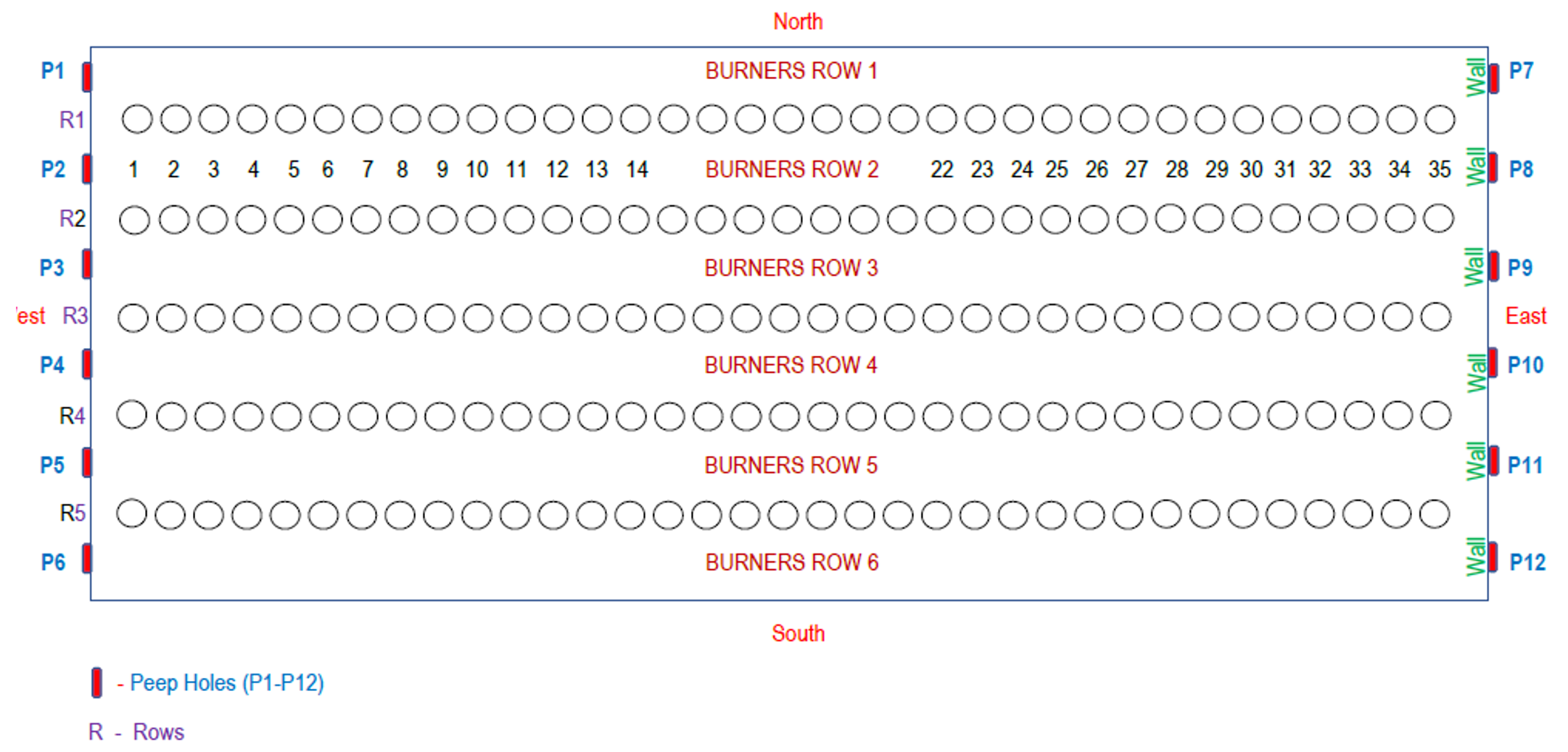
The furnace in the diagram above is created for explanation purposes only. Measurements will be taken on rows 1-2, tubes 5-10 and 25-30 in burners row 2. If tubes are accessible and measurable from tube 2+, take measurements from there.
DATA COLLECTION
- The large top-fired furnace in the diagram below is created for explanation purposes only as many questions we receive are based on this type of design. Measurements will be taken on rows 1-2, tubes 5-10 and 25-30 in burners row 2. If tubes are accessible and measurable from tube 2+, take measurements from there.
- Before starting, ensure the emissivity is set to 1 (ε=1) in the Cyclops. Corrections will be performed following the survey.
- Measure the peep door cooling effect at multiple locations using the method in the table below. Fix a Cyclops in place using a tripod and open the peep door, measure a single point on a single tube at 30 second intervals and record the values.
- Open peep door P2 and measure the reformer wall between rows 1 and 2 on the east side. This temperature is Tw (wall temperature) and will be used for the error correction for measured temperatures (Tm) taken for tubes 25-30.
- Open peep door P8 and measure the reformer wall in between rows 1 and 2 on the west side. This temperature will be used for the error correction for measured temperatures tm taken for tubes 5-10.
- Now that you have the wall temperatures on both sides, you are now ready to measure temperatures on tubes 5-10 and 25-30.
- Open peep door P2 and measure temperatures on tubes 5-10. Try to take the readings on the tubes at a fixed point, using the weld as a reference point if visible. If the weld is not visible, try to find a point of reference to ensure repeatability.
- Open peep door P8 and measure temperatures on tubes 25-30 and continue until all values are collected.
- After collecting your values, go to the Cyclops product page
- Using the Emissivity and Background Correction Calculator section, enter single or multiple values to “Measured temperature(s)”, leave the emissivity as 1, then enter the “Background Temperature”, and “Tube Emissivity”, press calculate, and the corrected values will populate automatically.
- Please note that there may be furnace types, designs, and conditions that this guide may not be suitable for, so guidance from process licensors should always be sought before making any adjustments based off tube metal temperature measurement data.
DOWNLOAD THE TUBE METAL TEMPERATURE (TMT) QUICK REFERENCE GUIDE HERE