Everyone knows that the opacity of a flue gas mixture cannot be negative, but opacity monitors still show negative readings. This article will explain the causes of the readings and some possible solutions.
Flue gas opacity readings range from 0%, when the sight path is completely clear, to 100% when it is totally obscured. Modern combustion processes typically have opacity readings below 5% so accuracy and stability are key operating parameters for any opacity monitor. Operators are understandably anxious when they see negative readings from their instrument so it is important to understand the most common causes for such readings.
Electronic noise and drift
All electronic instruments exhibit short-term noise and longer-term drift. In most cases, such effects are symmetric, with equal periods of positive and negative readings which average to zero. Worldwide standards for opacity monitors require the instrument to report both positive and negative readings so that the average value is calculated correctly in cases where the actual reading is at or close to zero.
Electronic drift cannot be eliminated, but a suitable averaging factor can greatly reduce the size of these effects.
Incorrect Calibration
Opacity monitors are focused and calibrated for a specific pathlength. It is important that the off-stack calibration setup closely matches the actual installation pathlength. Accepting the difficulty in matching the distances exactly, ASTM D6216 and other common standards allow for an uncertainty of +/- 2% in the installation pathlength. However any offset in the installation pathlength will result in an opacity offset.
The LAND 4500 MkIII exhibits around 1% opacity offset for every 1% change in the installation pathlength. An instrument which is calibrated on a shorter pathlength than the actual installation will show a positive offset whilst one calibrated on a longer pathlength will show a negative offset.
An inexpensive laser distance meter can be used to check the installation pathlength and is accurate to within a few millimetres. Using the same tool to verify the pathlength used for the off-stack calibration will minimise any errors.
 Contaminated Zero Reflector
Compliance
opacity monitors perform a daily check for zero and upscale drift and apply a correction so that long-term drift or dirty optics do not affect the reading. The drift check is performed by placing a reflector in front of the main lens and measuring the instrument’s response. The drift check assumes the zero reflector is clean and free of contamination. Any soiling or contamination of the zero reflector, for example because of condensation, will cause an elevated zero response. This will result in an over-correction and can cause a negative reading.
The
4500 MkIII has a foam seal which protects the reflector from contamination when it is not in use, and a sealed design minimises the risk of condensation within the device.
Thermal drift
Thermal drift occurs when some part of the instrument changes as a consequence of ambient temperature changes. Examples can include the transceiver light source, analogue electronics and retroreflector optics. Such changes can result in either positive or negative drift and can result in negative opacity readings. A well-designed opacity monitor will minimize the size of such effects and the widely-used ASTM D6216 standard requires a maximum uncorrected drift of 2% opacity for 21 °C change in ambient temperature. Tests show the 4500 MkIII drifts less than 0.25% opacity between -20 °C and 55 °C.
Misalignment
All stacks and ducts move to some extent as they heat up and cool down. An opacity monitor that is mounted to the stack will therefore change its alignment as the stack changes temperature. An important aspect of the optical design is therefore to minimise the effect of such changes on the measurement; the patented design of the
4500 MkIII light source ensures the retroreflector is evenly illuminated even if the instrument deviated ±0.25° from its ideal alignment. As a consequence, the opacity drift is <0.5% over this range. Depending on the initial alignment position, this can result in either positive or negative offset.
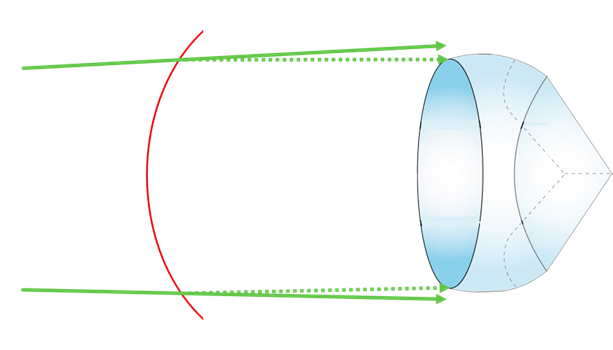
Gas Lens
One of the hardest effects to control is the so-called gas lens effect. This occurs because there is a curved interface between the cool purge air used to keep the optics clean and the hot flue gases. The change in density causes a weak lens to form and this means the retroreflector captures additional light when the process is operating compared to the intensity when it is cold.
This effect is small in most cases, but it can cause a negative offset greater than 1% opacity in stacks with a temperature above 300 °C.
Gas lens effects can be difficult to eliminate, but there are steps that can be taken to minimise their effect. Some people have suggested pre-heating the purge air to reduce the temperature difference between the purge air and the flue gases, but this tends to be impractical as it risks overheating the instrument it is designed to protect. It is more practical to reduce the velocity of the purge air where it enters the stack. This can be done by using the minimum amount of purge air needed to keep the optics clean and also by increasing the diameter of the standpipe used to mount the instrument. The standard
LAND standpipe is 57 mm in diameter. Increasing this to 89 mm by using a different standpipe design reduced the magnitude of a gas lens offset by a factor of 3 in one high-temperature application.
 Conclusions
We have discussed several effects which can cause negative offsets and therefore negative opacity readings.
The LAND 4500 MkIII has been designed to minimise effects such as temperature drift and misalignment, but factors such as the installation pathlength require careful attention to detail in the specification and installation at the individual installation point. The gas lens phenomenon can cause issues even for the most carefully-designed instrument, but we have identified steps that can be taken to minimise such effects.
For further information about the 4500 MkIII Opacity Monitor, click here